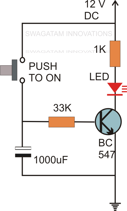
Question: Is there a solution where we can implement this without using any microcontroller, timer IC or any delay IC The circuit can contain resistors, capacitors, transistors or diodes etc. A SIMPLE passive-element time-delay circuit suitable for firing a silicon controlled rectifier is shown in. Once the charge from the capacitor is still preserved with time,when the push button is released,the transistor is switch on as a result of the electric field,and as such, the transistor the transistor activates the relay,which is used to drive any electric load. Problem: When DC supply (5V) is turned ON, the circuit gives 1 (5 V) for 2 seconds and then give 0 (0 V) for the rest of the time supply is connected. Normally a delay is made up of a high resistance and low value capacitor. SWITCH CIRCUIT: The switch circuit consist of the transistor and the relay coupled to a diode. The delay is made up of a 10k multi-turn pot and 10,000u electrolytic. Once the button is released, the switch circuit remains ON for little time, which as a result of the pull up resistor, which discharges the charge stored in the capacitor with time.

The timing of the delay can also be changed by changing the resistor value of VR1 and the capacitor value of E based on the time delay formula of t0.69RC. Charge from the capacitor is used to ON the switching circuit. This circuit uses a 555 timer to delay a pulse that comes in to a maximum time of 75 seconds. The capacitor stores its maximum electric charge,which is dependent on the capacitor value, once the button is pushed.

CHARGE STORAGE CIRCUIT: This circuit consist of electrolytic capacitor C2, and the pull up resistor. Once the button is pushed, the circuit instantly get triggered to delay the load in either switching ON or OFF.

TRIGGER CIRCUIT: The trigger circuit, consist of the push button only. doesn’t have the schematic, but I looked at the images and was able to piece this together and get it to work. So the time period after which this circuit. This circuit is very dirty DIRRRRRRTY and it’s great Incredibly simple, just a few parts. Due to the new CPLD and new software, our simple multiplexer circuit (written in Verilog) still works but has timing issues.
#Simple delay circuit series#
POWER SUPPLY CIRCUIT: The power supply circuit, consist of the 9v source from the battery, the 220uf electrolytic capacitor and the light indicator in series with the 220 ohm resistor,which show the presence of power in the system. The below figure is the schematic of a simple automatic on off timer with a fixed timing resistor and capacitor. The CPLD weve selected to use is the 3000A with a pin to pin delay of 10ns. The way this circuit works is when the signal in, line goes high and charges up the capacitor and turns on the transistor.


 0 kommentar(er)
